Introduction
You’re a proud pet owner, and on a nice Friday afternoon:
M: Hey George, how about grabbing some beers tonight, right after work? There will be some nice girls that we can impress with our programming skills!
G: Sorry dude, I have to go home and feed Rocky and Hulk, otherwise they’ll eat my furniture.
M: You suck, bro!
G: I know, I’m sorry!
If this (or a similar situation) has ever happened to you, and you’re a geek, this might be of your interest!
In this article I’m going to talk a little bit about the automatic pet food dispenser, and I’ll dig a little bit deeper into both mechanical and electronic design. I’ll also explain a little bit about the details for it’s physical construction. If you want just to build this thing, you can download the 3D physical design, the electronic schematic diagram, the PCB design and the firmware and you’re ready to go, but I want to focus this article on how I came up with the design, the decisions that I had to make regarding component choice and building materials and the variables that lead to those decisions. You can think of this as a little tutorial on how to design an electronic/mechanical gadget.
Description
We’re talking about a “dual pet food dispenser”, a device that feeds two bowls of food for two different pets on the same diet, although different quantities are allowed for each pet. The system would have a real-time clock keeping track of time, and the user can program an alarm, which when triggered at a specific programmed time, starts serving food through a mechanism that pulls food from a container, and another mechanism allows the food to be dispensed to the appropriate bowl.
The system would have a status LED as a visual indication that it’s turned on.
The user would interact with the system using four push-buttons: a button to select the function, a button to selected the parameter within the function, and two buttons (UP and DOWN) to increment or decrement the parameter being edited. The user would have feedback of his inputs by means of a 16×2 LCD display.
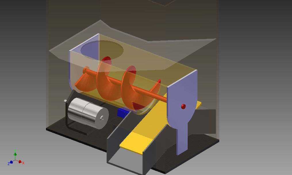
A 3D model of the device would look like this: The food would be placed in the upper container, fall through the circular hole into the pipe with the helix (in red) which would push the food to the other end and finally fall into one of both bowls, depending on the position of the bowl selector (in yellow).
User interface
The user’s input via the four push-buttons and the visual feedback through the LCD is designed in a menu-like fashion. The fist button iterates through all possible functions, the second button iterates through all possible parameters within a selected function, and the last two buttons modify the value being edited, as summarized in the following table:
Function                                     Parameter                    Up/Down
Display time/date                            N/A                          N/A
Display time/date when last dispensed        N/A                          N/A
Manual mode                                  Left bowl dispensing time    Enabled
                                             Right bowl dispensing time   Enabled
                                             Start/Stop                   Enabled
Set Timer 1                                  Hour                         Enabled
                                             Minutes                      Enabled
                                             Bowl A dispensing time       Enabled
                                             Bowl B dispensing time       Enabled
Set Timer 2                                  Hour                         Enabled
                                             Minutes                      Enabled
                                             Bowl A dispensing time       Enabled
                                             Bowl B dispensing time       Enabled
Set Time                                     Hour                         Enabled
                                             Minutes                      Enabled
                                             Seconds                      Enabled
Set Date                                     Day                          Enabled
                                             Month                        Enabled
                                             Year                         Enabled
Other nice features considered in the design:
- LCD backlight that turns off after 20 seconds of no user interaction
- Backup battery that saves the time and date in case of a power outage
- Up and Down buttons allow a long press for fast value increments/decrements
Electronic Design
Let’s start by sharing the electronic diagrams. Down here you’ll find the PROTEUS Isis schematic diagram used for testing the firmware. It’s important to notice that the hex code provided (see below) doesn’t work on the simulation, basically because it’s not the real processor. The simulation proved to be extremely useful for testing isolated portions of the code, however the full production code only works on the real hardware. Particularly I couldn’t get the I2C protocol to work on the simulation.
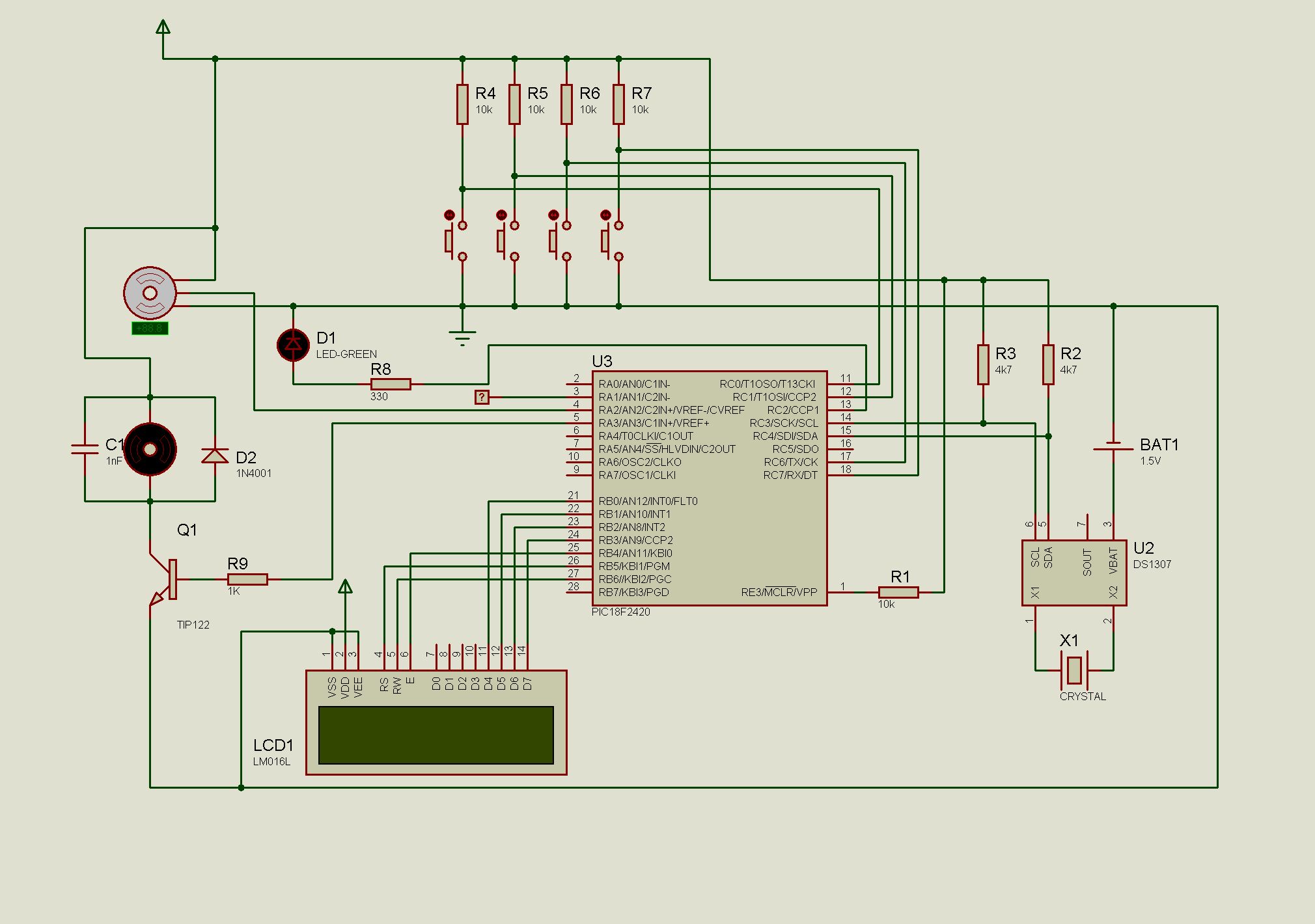
Click to download PROTEUS schematic
I wrote the schematic twice: the one above, and the schematic for the PCB design using EAGLE. Both schematics differ because for simulation we can omit a great deal of components, such as the power source details. The diagram for the PCB includes connection points for external components rather that components themselves, an example would be placing male jumpers instead of the LCD display (which will be connected to the jumpers with wires).


Click to download EAGLE PCB desgin (zip)
Click to download the hex file to write on the PIC MCU (zip)
Inputs and Outputs
The first thing you need to determine is WHAT and HOW the system does what it does, and how the user interacts with it. As you can read in the previous section, a simple yet appropriate system description in plain-English leads to determine the inputs and outputs and other features of the system. In the description above, I’ve highlighted in bold the keywords that lead to determine the I/O peripherals needed:
- Real-time clock – keeps track of time
- LED – visual indication of the system power state
- LCD display – give feedback to the user
- 4 push-buttons – allow the user to interact
- motor – get food from a container
- servo – select a bowl
Component choice, as explained further, is mainly based on price, availability, component reuse possibility, and available documentation.
Real Time clock
To have a real-time clock (RTC) you have many options: having a dedicated RTC chip, using your main MCU (with an additional crystal oscillator) and write some extra code, or even connect your device to the Web and get the time from a server. The last option is too far-fetched for my purposes while using the main CPU would have complicated the code by writing a bunch of date/time routines and keeping exact track of the CPU cycles and other complications (but it’s still possible).
I choose to have a dedicated chip with it’s own 32KHz crystal. Of the various options I found that the DS1307 was quite popular and it has a lot of related resources on the web, but most important, it’s available on local stores.
There are other chips that already have some alarm functionality built in, these can be very good alternatives to the design.
Most of these chips, including the DS1307, communicate using the I2C protocol. This is the very moment when I had to add the ‘I2C protocol’ to the list of features needed by the MCU.
Motors
The mechanical work is being done by two devices.
The first device spins an axis with a helix-shaped piece to make the food travel from the food container to an intermediate outlet. This device could be a stepper motor, a plain DC motor, a continuous servo or any other motor that you like. I’m planning to let the user select the food portion in terms of time, e.g., how many seconds should the motor spin to serve the food portion? For this purpose a plain old DC motor will do the job, I turn it on for the specified amount of time and tadaaa!… the food is on the table (if you prefer to let the user specify how many turns the device should make, then you could opt for a stepper motor).
I found a cheap 12V motor (reused from an old printer probably) with a very nice reduction gearbox having an output of ~0.3 rpm (or one revolution every 3 seconds) and a hell of a torque that makes it impossible to cause a motor-stall with bare hands.
The power transmission from the motor to the helix is achieved with gears and a belt. I did not use any bearings between the spinning parts and the frame, because I considered that I had enough torque to overcome any possible friction, and also because for such a slow speed, friction wouldn’t raise the temperature to a worrying level, but, needless to say, bearings are an enhancement you could add to your own design.
The second device positions a plate that makes the food travel from the intermediate outlet to any of the two bowls. For this you need to have a precise control of the angle, and once again, you can use a servo, a stepper motor, or even a plain DC motor (with some position feedback such as force-stop switches, optical switches, or any form of encoder). The easiest of course was the servo, which needs to be calibrated appropriately after installing, and for this purpose I included nice calibration routine in the firmware that is activated when plugging the device while pressing the FUNCTION button.
Other peripherals
The remaining peripherals to explain are the push-buttons, status LED and LCD display. I assume there’s no need to explain too much about the push-buttons or the LED: the push-buttons are simple circuit shorters, each MCU pin is connected to +5v via a pullup resistor, hence pushing the button grounds the pin driving it low. It’s important to note that the firmware includes some debouncing code for the buttons (debouncing could also be achieved in hardware, if you prefer). The LED might also need a resistor connected in series.
For the users feedback I decided to use a 16×2 LCD based on the very popular Hitachi HD44780 controller. There are many examples out there on how to drive such a display driver from a microcontroller, and you’ll find many different libraries on the web for pretty much any MCU flavor.
Power supply
Wait a second… you said 12v motor??? But the whole circuit runs on 5v! Yep, that means that the main power supply should be 12v, and we need to provide a step-down circuit using our good old friend the 7805, to bring the voltage down to 5v and have a dual (12v and 5v) power supply. I used an out-of-the-box 12v power supply that has a transformer, rectifiers and filters in one single piece.
Microcontroller Capabilities
Some of the important microcontroller capabilities I’m using are:
- PWM. Pulse Width Modulation is the technique used to drive the servo, and optionally you can use it to control the speed of the main motor. In my design, the motor at full speed coupled with the reduction gearbox is slow enough for my purposes so no PWM needed here. To drive the servo, on the other hand, I realized after many attempts (and as backed by many other people in blogs and forums) that generating a proper PWM signal (with a kinda-standard period of ~20ms) was rather tricky using the integrated PWM module combined witht the 4MHz crystal oscillator and the prescaler options from the PWM timer, that’s why I decided to generate the PWM signal for the servo with my own code using timers. As a side consecuence, the PWM module wasn’t doing any job so I used it to create a pulsing status LED that slowly fades in and out by changing the PWM duty cycle.
- Timers. The timers are probably the most important MCU features used, for the following purposes:
- Debouncing of push buttons
- Keeping track of a long press on a UP/DOWN button to rapidly increment or decrement a parameter’s value
- Turn off LCD backlight after 20 seconds of no user interaction
- Generate PWM to drive the servo (and optionally the motor, if you want it to run slower)
- I2C. If you want to talk to a man that only speaks chinese, then you have to learn chinese. If our real-time-clock talks I2C, then the MCU needs to talk I2C. The I2C protocol is a very clever way of having a bidirectional communication between two devices using only two wires, and is used widely by EEPROMs and our beloved real-time clock integrated circuit. The protocol itself is rather complex and you could eventually do without integrated I2C support, but why would you want to reinvent the wheel?
Which microcontroller to use?
The first challenge for any microcontroller driven circuit is to choose an appropriate microcontroller. Appropriate means not to small that it can barely cope with the demanded work and not to big that it would be like shooting a fly with a cannon.
This step is the core of the design but it’s considerably easier than you might think, it’s just a matter of knowing the device capabilities that you will be needing (timers, PWM modules, communication protocols, A/D conversion…) and a clear understanding of all the input and output ports (I/O pins) that you will be using. The inputs and outputs, as well as the device capabilities are described earlier.
Needless to say, you can use any microprocessor technology, the one you feel the most comfortable with, such as the popular Arduino and Atmel chips, Microchip and others. I decided to go for Microchip over Arduino because I’ve used the Microchip platform in the past and also because I think that Arduino it has two major disadvantages: first it’s expensive compared to Microchip, and second, I like to have more control and better understanding of the bits and bytes of the firmware and the electronic design.
My design is built around the PIC18F2420 microprocessor from Microchip. To come up with this choice, I looked up in the Microchip’s website, filtered all MCUs using criteria such as: having at least the number of I/O of pins needed, I2C availability, PWM module, number of timers, flash memory size (very important) and EEPROM size. I came up with a reduced list of options. I wrote down a couple of the smallest ones fitting my criteria and went to the store. Picking the smallest is easy because the smart Microchip web site designers/programmers list all microcontrollers in an order based on price by default, so, in a way, the first ones listed should be your best options. The PIC18F2420 was my second option, because my first option (don’t remember which one) was not available locally.
The construction process for the electronics is pretty much self-explanatory for those who have some experience building electronic stuff. Just etch the PCB, solder all components, burn the firmware in the microcontroller, connect the motors and other peripherals to the PCB using headers and you’re ready to go.
Mechanical Design & Construction
There are many different mechanical ways of dispensing food to your pet. I considered, amongst others, a conveyor belt, a screw shaped device, a mill-type thing… just let go your imagination. I went for the screw shaped device to push the food, and a tilted plate to select direction, as shown in the 3D models.


The difficult thing about a home-made mechanical design is that you can’t really have a precise mechanical design until you have pretty much all electronic components in hand. For example, you know you need a 12v motor, but you don’t know how it will look like until you have it in your hands, especially when you’re reusing parts from old printers. Motors have screw holes to attach them to their enclosure, but they can come in many different shapes or positions. Needless to say this problem also holds for servos, LCD and even the PCB. The bottom line is: you design the enclosure and the whole physical assembly once you have certainty of the components you’ll use, and, in fact, for me the physical design was a cyclical process where I had to modify the design as I was building it.
The two main mechanic parts are the motor that drives the helix, and the servo that drives the bowl selector.
The helix (and its shaft) is a two-piece 3D printed part: two parts resulting from cutting the piece along it’s axis, mainly because the 3D printer can’t easily print everything in one single piece. This piece is enclosed in a U-shaped structure made using an acrylic 3″ pipe (as explained further) and driven by the 12v motor via a belt.

Download STL files for 3D printing
The bowl selector is driven by a servo as you can see in the following image, which is pretty much self-explanatory.

The structure, enclosing case, and pretty much the whole thing is built out of acrylic (plexi glass). I had some nice acrylic sheets (3mm and 4mm thick) at home, so this was the main reason for this choice, and a very convenient one since it’s an easy yet robust material to work with and, as an additional advantage, you don’t need very sophisticated tools to cut and shape the sheets. I used some very basic gear: a hand saw, sandpaper, drill, and a torch to bend the acrylic. If you have access to laser cutter and other nice tools the job will be easier and hopefully more precise.
Another design bullet on my wishlist was the fact that I wanted the device to be transparent so I could see the guts of the device while working, it’s a nice spectacle! Needless to say you can work with any material of your choice.
All acrylic parts are either screwed or glued to each other. The choice between glue and screws is only dependent on the assembly process, e.g., I should be able to disassemble the whole machine to access, modify, change some of the parts. Parts that might stay together during assembly/disassembly are glued to each other, parts that need to be separated are joined using screws. Make sure you use acrylic glue or cement; I tried superglue resulting in white-ish stained parts, and I tried another very good epoxic substance but it’s messy and takes more than 10 hours to dry and cure.
Also be careful when you make holes in acrylic, because it melts due to the friction heat. I ran into problems when stopping the drill while making holes, because the acrylic would melt and then solidify stuck to the bit. Sometimes to remove the bit I had to break the acrylic part, throw it to the trash can, and start the part from scratch.
Problems Encountered
Obviously building this thing couldn’t go without any bugs. And I’m not talking about firmware bugs that are easy to solve by correcting the code, compiling, burning in to the chip and running. I’m talking here about major issues.
The biggest problem I encountered was related to the food getting stuck in the container and not wanting to fall through the circular hole into the U-shaped pipe. My good old friend Manuel predicted I would have this problem and suggested to add some vibrator to the food container, this would make the food shake and fall. I tried with some vibrators connected in parallel with the main motor and physically attached to the container in different ways but the problem was still there. The solution I found was to stir the food by adding a shaft with some screws inside the food container. This shaft is driven by the main motor for which I replaced the original short belt for a long one that would drive both the helix and the stirring shaft, as you can see in the following image. In the video you can see this piece at work.
